| |||
|

|
Test Data |
Below you shall see step-by-step description of an experiment made on NTM Voltage Stabilizer. |
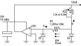
The last experiment was made over Voltage Stabilizer. This device fully illustrates the whole principle. If you could understand how it works, it is not difficult to explain the framework of any other NTM device. So, here you see just a short table, which shows the test data of voltage dependence on temperature, as it is the most common event.
It is perfect quality of stabilization, even if used an single-supplied op-amp with very bad characteristics (bad offset voltage). As you know, UD1 must be zero volts (if the circuit is in balance, when op-amp exactly detects zero), but with the temperature it varied from -0.2V to +0.2V ! It were not used exact precision devices to calibrate the circuit (finding the values of R1 and R2). We offer to you to repeat this simply experiment, based on the patent BY1860C1, and even without exact calibrating you will see the effect of stabilization. By the way, you will have the ABSOLUTE sustem on your table. A.Stratilatov |
| INTRODUCTION |
| Again, We need to say, why this stabilizer is naturally better than any of all known voltage regulators and what is the main difference between usual stabilizers and this new. It is because all known methods of voltage stabilization, EXCEPT ONE (called "current mirror"), HAVE THE REFERENCE in its self. Even the most exactliest voltage stabilizer "current mirror" has a thing which made him complete expensive and not too precision, it is that it needs a pair of transistors with identical parameters, what is hard to be made, and the precision of regulation is highly dependent upun the difference between both transistors. Each of known voltage stabilizers HAS COMPARING CIRCUIT IN ITS SELF. But the New has the same elements (blocks) except reference and there isn`t a necessity to use any pair of identical elements (elements with identical characteristics). |
| Step one |
| Build-up | ||||||
|
| Step two |
| Calibrating | ||||||||||||||||||||
After the building, I choosed R1 at any value (for example 1,2Mohm) and then I was changing the temperature of optocouopler (for 0.5 degree per second) and controlled the value of Uout. Uout was changing up or down (it does not metter, for example it was falling down), while the temperature was increasing. So, the Uout was decreasing while the temperature was increasing. Then I decreased the temperature of optocoupler downto +20 degree celsius, the Uout has increased also. I changed the value of R2 (potentiometer) and saw, that when I was increasing the temperature of optocoupler again (about 1/2 degree per second), the voltage Uout was increasing too. Accordngly the temperature coefficient Tk of my voltage stabilizer, as you can see, was <0 in the first case and then (the second case) it was >0. If there is Tk<0 and there is Tk>0 then there must be Tk=0. I just found Tk=0 by choosing R2 (potentiometer). Accordingly, if Tk=0 then Uout has a constant value. I did not changed the value of R1 h
|
| Step three |
| Test Data |
|
I think it is not so hard to repeat my experiment even using your most different op-amps and optocoupler. In case if you will not get any even a little good result from your modelling, please let me know. But I am sure that you will work it. I`d like to see your test data and if you have it or you have any question or comment, please tell me. For information about how to find me, see feed-back page or send me email. |
|
ADVERTISING
|
This site is private property not for copy, sale or rental until you have unless money. All matherials on this site are for personal use only.
© Alexey Stratilatov 1998, [email protected]. |